Page 37 May June 2014 TCA
P. 37
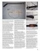
Figure 3: 70cm driven element mounting.
Figure 2: Antenna components before assembly. Figure 5. Note that the braid of the coax is
connected to the centre of the driven Figure 4: Typical 2m element mounting.
Epoxy might work better, but future builds element and the centre conductor is
will employ the method used for securing connected to the end. The centre of the
the 70 cm driven element. element is a voltage null and feeding
The driven element is the only element thusly eliminates the need for fancy
that is not secured with adhesive. I soldered gamma matching. The standing wave ratio
ring terminals onto the end and midpoint, (SWR) can be checked for each
being sure to subtract some length for the frequency and, if necessary, adjusted by
width of the boom. Figure 3 shows the trimming the open end of the driven
ring terminal confguration fastened to the element. If you don’t have the means to
fnished antenna. The ring terminals check SWR, don’t worry; building the
provided a place to secure the element to antenna to the dimensions given should
the boom and they make convenient provide a very close match and the true
points to attach the feedline coax. Any test will come when you actually operate.
future build will use this method to secure The Diplexer Figure 5: Diplexer mounted to antenna.
the parasitic 70 cm elements as well.
Satellite antenna’s are crossband “Writing a program to work the formulas
Install the 2 metre Elements antenna’s that require a diplexer to split and tables was a great time saver,” he
The 2 metre refector and director used the frequencies to ensure the radio said. “I wrote them as web-based apps so
I could use a web browser and make them
the mounting hardware from the original frequency (RF) energy goes to, or comes available to anyone with Internet access.”
TV antenna and a bolt through the boom from, the intended portion of the antenna.
as shown in Figure 4. I did not have a third To split the frequency, diplexers are Heatherington’s calculator requires
bracket from the old TV antenna and installed in the feedlines between the several inputs from the user: design cutoff
running a bolt through the boom would radio and the two antennas. Diplexers use frequency, number of poles and
have shorted the driven element to itself a combination of high pass and low pass characteristic impedance.
so it is attached with separate, short wood flters to split the frequencies. Figure 6 Cutoff frequency is the point at which the
screws at the top and bottom. Both locations shows a typical diplexer circuit using flter has attenuated the incoming signal to
in the element were pre-drilled with inductors and capacitors (L and C) based the half-power point or three decibels (dB).
clearance holes and I used a vice to on values that I had available. Since satellites operate with an uplink
fatten the tubular aluminum to provide fat While designing my diplexer I found very frequency around 144 MHz and a downlink
mounting surfaces. Once constructed I little information to help me. Fortunately frequency around 430 to 450 MHz, a cutoff
found the 2 metre driven element did not Dale Heatherington, WA4DSY, has a frequency anywhere from 225 to 375 MHz
remain square to the boom so I added a calculator application on his website for should produce acceptable results. I used
plastic angle bracket to the boom and used designing LC low pass and high pass circuits, a design cutoff frequency of 300 MHz.
electrical tape to secure the element to it. which simplifed the process. I emailed Heatherington cautions that the calculator
FEEDING THE ANTENNA Dale to fnd out if he could clear up some produces component values that are
of the mystery surrounding flter design. ideal, not necessarily values that you will
Coax Feedpoint Connection He told me that he originally programmed fnd in your parts box. “Users have to
the calculators for his own use because tweak the parameters until they get a
To feed the antenna, simply attach coax to manually calculating flter component
the centre of the driven element and the values was labour intensive. compromise between rational parts values
end of the half-folded dipole as shown in and performance,” he said.
35