Page 18 January February 2018 TCA
P. 18
Bluetooth Alan’s videos, but nevertheless, with Originally, these boards plugged into the
enough time and patience, I have been blue sockets now mounted at the top of
I found the column “Eclectic Technology” pleased to be able to repair some radios the boards. I cut the traces to the bottom
in the November 2017 issue of QST really and other equipment. My latest attempt pins and connected wires from top to
fascinating. According to this column by was to fix the S‑meter on my old Yaesu bottom. In use, the extender boards plug
Steve Ford, WB8IMY, the originator of FT‑ONE transceiver. On this radio there into the FT‑ONE chassis and the FT‑ONE
Bluetooth, Jim Kardach of Intel, was are two front panel meters: one measures circuit board plugs into the blue sockets.
reading a history of the Vikings at the time the final amplifier voltage and current and Two extender boards are required
he developed this protocol in 1997. forward and reflected power; and the because in the FT‑ONE most of the circuit
Kardach was impressed with King Harald, other meter measures signal strength and boards have two sets of connectors.
the Danish king who united the Danish ALC. Recently, the S‑meter stopped
tribes in the 10th century and he thought working properly. Most of the time it Now, with the IF unit mounted in these
that Harald’s nickname “Blatand”, which wouldn’t work at all, but sometimes it extender boards I was able to measure
translated into English as “Bluetooth”, would gradually start showing some the voltages in the vicinity of Q 9025 , the
would be a good name for this system response. After a little more time, it would MC3403P quad op‑amp. By comparing
that united so many ways of short‑range start working properly but unfortunately the schematic in Figure 2 with the data
communication between devices. this wouldn’t last very long. sheet for the MC3403, I could identify the
Repairing Equipment To fix this problem I began by looking at pins for the four sections of the op‑amp
and outline their functions. If, as sometimes
In a previous column I mentioned Alan the technical manual that came with the happened, the S‑meter started working
Wolke, W2AEW, when I described some radio and I found the following text: normally as I was taking measurements,
of the many YouTube videos that he has “The AGC signal from Q9022 is fed to I tried to compare my voltage
produced on a great variety of subjects quad differential input op amp Q9025 measurements with the non‑working
related to Amateur Radio. Alan is an (MC3403P), from where it is applied to situation as best I could.
Engineer who works for Tektronix, and it the RF and IF amplifiers, the scanner The only place I noticed a definite difference
is evident from the manner in which he circuitry (for automatic scan stop) and the was at the edge connector, pin #32,
presents his subject, and the clear S‑meter.” This is where I began my search labelled SM on the diagram in Figure 2,
explanations that he provides, that he is a for the problem. leading from the circuit board. When the
very knowledgeable presenter. You can Since the FT‑ONE construction is based S‑meter was working, the voltage
find a list of the videos that he has made on a number of interconnected plug‑in measured at this pin was variable, but in
at http://www.qsl.net/w2aew/youtube/ circuit boards, I first had to remove the IF the range of 50 mV. When the S‑meter
W2AEW_video_index.pdf. Amongst his unit on which the S‑meter circuitry is was not working the voltage at this pin
many videos are some in which he located and mount it into extender boards. was about 0.67 V.
explains how he goes about fixing some I don’t have the extender boards made for
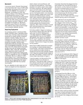
radios: for example an Icom IC‑706MkIIG; the radio, but instead, I made do with the You can see the actual pin #32 in Figure 3
a Kenwood TM‑710; a Yaesu FT‑7800; home‑made ones shown in Figure 1. on the next page. It is the metal tab of the
and a Yaesu FT‑817. I have learned a edge connector third from the right at the
great deal from watching his procedures I was fortunate to find the parts for the bottom of the Figure.
and the way he approaches the repair extender boards in an old piece of
of these radios with their tiny surface equipment. They had the right number of It was this observation that the S‑meter
mount parts. pins with pin spacing near enough to the voltage was 0.67 V when the meter was
correct distance to work, and the length not working, and in the range of 50 mV
My own attempts at radio repair are not from top to bottom was adequate too. when it was working, that should have
nearly as elegant as those depicted in been the immediate clue as to where the
problem might lie. It still took me a while,
however, to really analyze what was
going on.
Tracing back from the SM pin on the
circuit diagram you will see D near the
53
top right edge of Figure 2. The forward
voltage of a diode like this one is about
0.67 V. With a fault in the connection
between the SM pin and the meter, no
current will flow through the meter and the
voltage at the S‑meter pin will rise to the
forward conduction voltage of the diode
as it was doing in my radio when the
S‑meter was not functioning.
With the meter working properly, the diode
no longer conducts because the meter
offers a low resistance path to ground.
In this situation the voltage at the S‑meter
pin is low.
Figure 1: Home-made extender boards that allow measurements to be made while circuit
boards are raised up out of the FT-ONE transceiver.
16