Page 23 January February 2018 TCA
P. 23
VLF Adventures: Spanning the Atlantic on 36,000 metres
Joe Craig, VO1NA The next day, using
Spectrum Lab software
For almost a century, Radio Amateurs by Wolf, DL4YHF and a
were confined to the “useless wavelengths” Mini Whip antenna
of 200 metres and down. Of course, we designed by Roelof,
proved the utility of shortwave by PA0RDT, CW signals
spanning the Atlantic in the 1920s, but the
lower boundary of our spectral playground were heard on 8.277 kHz
was fixed to MF and up until recently. at 200 metres from the
100m‑long wire
Thanks to Radio Amateurs of Canada and transmitting aerial.
the efforts of members of the Marconi
Radio Club of Newfoundland (MRCN) and The setup was very
Amateurs all over, we now enjoy an unconventional: a small
additional MF band at 630 metres and our active antenna was
first LF band at 2200 metres. plugged into the sound
card of a portable
Some Canadian Radio Amateurs built computer configured as a
their own gear to experiment on the long software defined receiver.
waves. They made observations to CW at 500 Hz was heard
support RAC delegations at the on the computer speaker,
International Telecommunication Union digitally down‑converted
(ITU) conferences that resulted in our new from a radio wave
bands. They were looking for a new frequency that was just
challenge and VLF (3‑30 kHz) was next an octave above the high
on the list.
C on a piano.
Now confined to the waves 2200m and An old 70 watt stage
down, we pondered how to become amplifier designed by the
authorized to transmit below 30 kHz.
Frequencies below 9 (and later 8.3 kHz) late Canadian Pete
were not allocated and seeking Ministerial Traynor was used as the
approval for VLF transmissions proved final amplifier with the
challenging. I tried various mathematical volume at level at three.
contortions to formulate a proposal that A frequency synthesizer,
could be accommodated under the clocked by a dual oven Figure 2: Reception in the far zone. Note the
legislation; others tried different means crystal oscillator and programmed with an small iceberg in the background.
but, in the end, none was successful. Arduino Uno microprocessor generated
With the latest Canadian Table of the carrier. The Uno also took care of the one, otherwise it can get expensive.
Frequency Allocations (http://www.ic. CW keying. A competent and resourceful scrounger
gc.ca/eic/site/smt‑gst.nsf/eng/sf10759. At a mean height of 12 metres, the aerial will do what I did: find a source of copper
html#t1) came explicit provisions for was extremely small in terms of and tinker a lot. Discarded coils from
experimentation below 8.3 kHz. expendable bathythermographs (XBTs)
wavelength: two percent is considered sometimes have lots of wire left on them.
In June 2014, a VLF letter of authorization infinitesimal in the standard antenna A friendly oceanographic technician was
(LOA) was on the wall in my shack theory texts. This aerial was two percent happy to have me take them from his
prescribing 10 mW ERP from 8.0 to 8.3 kHz. of this. The length provided top loading shop. XBT wire is very fine at 0.08
and improved the radiation by making the millimetres in diameter so 24 strands were
vertical current distribution more uniform wound in parallel to handle the current.
than had the antenna just been a 12 metre A pie configuration was used to optimize
vertical element. I coined the term the inductance per length of wire. Voltage
“Rotated L” (RL) to describe an aerial for handling was quite another matter as was
which the horizontal portion is much later discovered. The tuning coil for the
longer than the vertical. By contrast, the initial experiment consisted of a tissue roll
conventional inverted L uses a relatively wound with wire placed over an XBT
shorter horizontal portion to make the spool. It did not tolerate the very high
feedpoint impedance closer to 50 ohms voltages very well.
and its overall length is somewhat greater
than a quarter wave. The following summer I endeavoured to
detect signals outside the so‑called near
Convincing the RL to accept VLF RF is zone, 5.6 kilometres away. Within this
challenging. The RF sees tens of k‑ohms region, the signal reaches the receiver
of capacitive reactance that must be tuned primarily through inductive and electrostatic
out with a very large coil. I used 0.5 H. coupling rather than radiation. Despite
If you have a very long – one or two valiant efforts, the signals could not be
Figure 1: Mini Whip active antenna (left) and kilometres – piece of wire, you can wind
VLF direct conversion receiver. detected beyond 5.2 kilometres.
21
Joe Craig, VO1NA The next day, using
Spectrum Lab software
For almost a century, Radio Amateurs by Wolf, DL4YHF and a
were confined to the “useless wavelengths” Mini Whip antenna
of 200 metres and down. Of course, we designed by Roelof,
proved the utility of shortwave by PA0RDT, CW signals
spanning the Atlantic in the 1920s, but the
lower boundary of our spectral playground were heard on 8.277 kHz
was fixed to MF and up until recently. at 200 metres from the
100m‑long wire
Thanks to Radio Amateurs of Canada and transmitting aerial.
the efforts of members of the Marconi
Radio Club of Newfoundland (MRCN) and The setup was very
Amateurs all over, we now enjoy an unconventional: a small
additional MF band at 630 metres and our active antenna was
first LF band at 2200 metres. plugged into the sound
card of a portable
Some Canadian Radio Amateurs built computer configured as a
their own gear to experiment on the long software defined receiver.
waves. They made observations to CW at 500 Hz was heard
support RAC delegations at the on the computer speaker,
International Telecommunication Union digitally down‑converted
(ITU) conferences that resulted in our new from a radio wave
bands. They were looking for a new frequency that was just
challenge and VLF (3‑30 kHz) was next an octave above the high
on the list.
C on a piano.
Now confined to the waves 2200m and An old 70 watt stage
down, we pondered how to become amplifier designed by the
authorized to transmit below 30 kHz.
Frequencies below 9 (and later 8.3 kHz) late Canadian Pete
were not allocated and seeking Ministerial Traynor was used as the
approval for VLF transmissions proved final amplifier with the
challenging. I tried various mathematical volume at level at three.
contortions to formulate a proposal that A frequency synthesizer,
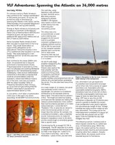
could be accommodated under the clocked by a dual oven Figure 2: Reception in the far zone. Note the
legislation; others tried different means crystal oscillator and programmed with an small iceberg in the background.
but, in the end, none was successful. Arduino Uno microprocessor generated
With the latest Canadian Table of the carrier. The Uno also took care of the one, otherwise it can get expensive.
Frequency Allocations (http://www.ic. CW keying. A competent and resourceful scrounger
gc.ca/eic/site/smt‑gst.nsf/eng/sf10759. At a mean height of 12 metres, the aerial will do what I did: find a source of copper
html#t1) came explicit provisions for was extremely small in terms of and tinker a lot. Discarded coils from
experimentation below 8.3 kHz. expendable bathythermographs (XBTs)
wavelength: two percent is considered sometimes have lots of wire left on them.
In June 2014, a VLF letter of authorization infinitesimal in the standard antenna A friendly oceanographic technician was
(LOA) was on the wall in my shack theory texts. This aerial was two percent happy to have me take them from his
prescribing 10 mW ERP from 8.0 to 8.3 kHz. of this. The length provided top loading shop. XBT wire is very fine at 0.08
and improved the radiation by making the millimetres in diameter so 24 strands were
vertical current distribution more uniform wound in parallel to handle the current.
than had the antenna just been a 12 metre A pie configuration was used to optimize
vertical element. I coined the term the inductance per length of wire. Voltage
“Rotated L” (RL) to describe an aerial for handling was quite another matter as was
which the horizontal portion is much later discovered. The tuning coil for the
longer than the vertical. By contrast, the initial experiment consisted of a tissue roll
conventional inverted L uses a relatively wound with wire placed over an XBT
shorter horizontal portion to make the spool. It did not tolerate the very high
feedpoint impedance closer to 50 ohms voltages very well.
and its overall length is somewhat greater
than a quarter wave. The following summer I endeavoured to
detect signals outside the so‑called near
Convincing the RL to accept VLF RF is zone, 5.6 kilometres away. Within this
challenging. The RF sees tens of k‑ohms region, the signal reaches the receiver
of capacitive reactance that must be tuned primarily through inductive and electrostatic
out with a very large coil. I used 0.5 H. coupling rather than radiation. Despite
If you have a very long – one or two valiant efforts, the signals could not be
Figure 1: Mini Whip active antenna (left) and kilometres – piece of wire, you can wind
VLF direct conversion receiver. detected beyond 5.2 kilometres.
21