Page 37 January February 2018 TCA
P. 37
A Remote Controlled Wi-Fi Antenna Switch
Horacio Bouzas, VA6DTX Eight GPIOs means that we can program A 74HC238 3‑to‑8 line decoder provides
the module so it can read and write digital the logic to switch the outputs. The
signals – a 0 or a 1; or a few millivolts or commands are sent from the ESP8266
3.3 volts – on these GPIOs. This is perfect GPIOs. The 74HC238 outputs drive a
to drive LEDs or relays and make them ULN2803 Darlington power driver; the
open or close according to some logic and ULN2803 controls the relays and the
control, either running on the module or indicator LEDs.
instructed via a web or TCP server.
Table 1 shows how the GPIOs from the
The module also features a serial interface ESP8266 would be driving the 74HC238.
so you can communicate with it to program GPIO0 and GPIO2 are the outputs from
or debug it. the ESP8266 being fed to the inputs of the
74HC238, and Relay1 to 4 are the outputs
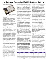
Figure 1: The ESP8266 There is plenty of material out there to get
ESP-12Wi-Fi anyone going with this little wonder. You of the 74HC238 being fed to the ULN2803.
Micro-Controller Module will need a USB to serial module to initially The outputs of the ULN2803 are then
Introduction talk to the ESP8266, and you should also driving the relays and the indicator LEDs.
be familiar with serial communication and Monitoring the Output State
This article describes the design and be able to do some script programming.
construction of a remote Wi‑Fi Antenna Since we are limited in ESP8266 GPIOs
Switch for HF that is an order of For the USB to serial module, any to use as digital inputs, I used the
magnitude more economical than any FTDI232‑based module should work, but 74HC4052 multiplexer to alternate
wireless remote switch available today. be careful as there are counterfeit between outputs and to send the state to
It is limited in its power handling and FTDI232 modules that can render them one single GPIO in the ESP8266.
frequency bandwidth, but I believe it is of useless. Make sure whatever you get is Schematics and Circuit Description
great use for most Amateur Radio genuine.
operators. You need to choose a serial terminal to I split the antenna switch into two
send commands to the serial module that modules: the control module and the
The ESP8266 Wi-Fi Micro-Controller will send commands to the ESP8266. connector/relay module. The schematics
Module: A Little Wonder Something like CoolTerm – available at for the control module and for the
http://freeware.the‑meiers.org/ – would do connector/relay module can be found on
The core control processor for the switch the job. I use CoolTerm mostly on the my website along with detailed information
is a Wi‑Fi enabled microcontroller from Mac. In addition, when you start copying on how the circuits work.
Espressif with a very small footprint, the LUA code into the module, CoolTerm does
ESP8266. It can be programmed using a great job. You can find more information, The Final Product
standard C language by flashing it with programming code examples and I programmed the ESP8266 so it can be
the manufacturer’s software development detailed instructions about setting up configured via a web browser to connect
kit (SDK). But it can also be programmed and programming the ESP8266 on my to the Wi‑Fi router. Once configured, the
in LUA using the NodeMCU SDK (open website at http://www.horaciobouzas.com. module acquires an IP address and then I
source, just Google it or go to GitHub at can communicate via TCP or HTTP
https://github.com/). With this brief introduction to the protocol. The module responds to the
ESP8266, you can start having a lot of fun
LUA is a scripting language used widely in prototyping all kinds of interesting Wi‑Fi simple commands 1, 2, 3 and 4 to switch
the gaming industry and I picked it to projects. For example, if you have between the antennas.
program the ESP8266 because it is equipment that you can control with digital The command to switch the relays can be
compact, very high level and allows me to signals, like a tuner, you can easily build a sent using a web browser or TCP
use rapid prototyping. remote switch that can do the job! commands can be sent from a laptop or
computer using a simple utility written in
The ESP8266 acts as an access point Design deliberations for driving the
and/or a Wi‑Fi station so once it is relays of the antenna switch module Python, for example. If using a mobile
device, there are apps that send and
configured it acquires an IP address receive TCP commands. But better yet,
and then you can communicate with it This first implementation is focused on the I went ahead and wrote an iPhone app
via a web browser or a TCP connection 100 to 300 Watts power range. The
(phone, tablet, computer, etc). ESP8266 has enough GPIOs to handle that specifically pairs nicely with the
four relays. I also wanted to be able to antenna switch. A simple command string
The ESP8266 comes in many different remotely find out the status of the switch “status” returns the status of the outputs
packages, depending on the number of at any time by monitoring the state of the as a string of the form: 0,0,1,0 (output 3
I/O ports you want to have access to. outputs. is ON).
Figure 1 shows the ESP8266 ESP‑12
which is the one I’ve chosen for the GPIO0 GPIO2 Relay1 Relay2 Relay3 Relay4
project. It has eight available GPIOs L L H L L L
(input/output ports or general purpose
input/output) available, which was not H L L H L L
enough for this application, but that was L H L L H L
all I had.
Table 1: This table illustrates how the GPIOs from the ESP8266 would be driving the 74HC238.
35
Horacio Bouzas, VA6DTX Eight GPIOs means that we can program A 74HC238 3‑to‑8 line decoder provides
the module so it can read and write digital the logic to switch the outputs. The
signals – a 0 or a 1; or a few millivolts or commands are sent from the ESP8266
3.3 volts – on these GPIOs. This is perfect GPIOs. The 74HC238 outputs drive a
to drive LEDs or relays and make them ULN2803 Darlington power driver; the
open or close according to some logic and ULN2803 controls the relays and the
control, either running on the module or indicator LEDs.
instructed via a web or TCP server.
Table 1 shows how the GPIOs from the
The module also features a serial interface ESP8266 would be driving the 74HC238.
so you can communicate with it to program GPIO0 and GPIO2 are the outputs from
or debug it. the ESP8266 being fed to the inputs of the
74HC238, and Relay1 to 4 are the outputs
Figure 1: The ESP8266 There is plenty of material out there to get
ESP-12Wi-Fi anyone going with this little wonder. You of the 74HC238 being fed to the ULN2803.
Micro-Controller Module will need a USB to serial module to initially The outputs of the ULN2803 are then
Introduction talk to the ESP8266, and you should also driving the relays and the indicator LEDs.
be familiar with serial communication and Monitoring the Output State
This article describes the design and be able to do some script programming.
construction of a remote Wi‑Fi Antenna Since we are limited in ESP8266 GPIOs
Switch for HF that is an order of For the USB to serial module, any to use as digital inputs, I used the
magnitude more economical than any FTDI232‑based module should work, but 74HC4052 multiplexer to alternate
wireless remote switch available today. be careful as there are counterfeit between outputs and to send the state to
It is limited in its power handling and FTDI232 modules that can render them one single GPIO in the ESP8266.
frequency bandwidth, but I believe it is of useless. Make sure whatever you get is Schematics and Circuit Description
great use for most Amateur Radio genuine.
operators. You need to choose a serial terminal to I split the antenna switch into two
send commands to the serial module that modules: the control module and the
The ESP8266 Wi-Fi Micro-Controller will send commands to the ESP8266. connector/relay module. The schematics
Module: A Little Wonder Something like CoolTerm – available at for the control module and for the
http://freeware.the‑meiers.org/ – would do connector/relay module can be found on
The core control processor for the switch the job. I use CoolTerm mostly on the my website along with detailed information
is a Wi‑Fi enabled microcontroller from Mac. In addition, when you start copying on how the circuits work.
Espressif with a very small footprint, the LUA code into the module, CoolTerm does
ESP8266. It can be programmed using a great job. You can find more information, The Final Product
standard C language by flashing it with programming code examples and I programmed the ESP8266 so it can be
the manufacturer’s software development detailed instructions about setting up configured via a web browser to connect
kit (SDK). But it can also be programmed and programming the ESP8266 on my to the Wi‑Fi router. Once configured, the
in LUA using the NodeMCU SDK (open website at http://www.horaciobouzas.com. module acquires an IP address and then I
source, just Google it or go to GitHub at can communicate via TCP or HTTP
https://github.com/). With this brief introduction to the protocol. The module responds to the
ESP8266, you can start having a lot of fun
LUA is a scripting language used widely in prototyping all kinds of interesting Wi‑Fi simple commands 1, 2, 3 and 4 to switch
the gaming industry and I picked it to projects. For example, if you have between the antennas.
program the ESP8266 because it is equipment that you can control with digital The command to switch the relays can be
compact, very high level and allows me to signals, like a tuner, you can easily build a sent using a web browser or TCP
use rapid prototyping. remote switch that can do the job! commands can be sent from a laptop or
computer using a simple utility written in
The ESP8266 acts as an access point Design deliberations for driving the
and/or a Wi‑Fi station so once it is relays of the antenna switch module Python, for example. If using a mobile
device, there are apps that send and
configured it acquires an IP address receive TCP commands. But better yet,
and then you can communicate with it This first implementation is focused on the I went ahead and wrote an iPhone app
via a web browser or a TCP connection 100 to 300 Watts power range. The
(phone, tablet, computer, etc). ESP8266 has enough GPIOs to handle that specifically pairs nicely with the
four relays. I also wanted to be able to antenna switch. A simple command string
The ESP8266 comes in many different remotely find out the status of the switch “status” returns the status of the outputs
packages, depending on the number of at any time by monitoring the state of the as a string of the form: 0,0,1,0 (output 3
I/O ports you want to have access to. outputs. is ON).
Figure 1 shows the ESP8266 ESP‑12
which is the one I’ve chosen for the GPIO0 GPIO2 Relay1 Relay2 Relay3 Relay4
project. It has eight available GPIOs L L H L L L
(input/output ports or general purpose
input/output) available, which was not H L L H L L
enough for this application, but that was L H L L H L
all I had.
Table 1: This table illustrates how the GPIOs from the ESP8266 would be driving the 74HC238.
35