Page 17 May June 2014 TCA
P. 17
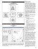
Figure 1: Simulation Block Diagram SIMPLE CIRCUITS
SimSmith Process SimSmith is a fairly complex simulation
Program Collects Load Data program that is easy to use if you proceed
Transmission Line Data from TLDetails one step at a time rather than attempting
to deal with a complex analysis of a big
antenna system. For this reason, I recommend
that you start with simple circuits and add
components and functions one at a time
to create building blocks for further use.
You can fnd simple circuits in the tutorials
that are given on the SimSmith website.
There is always a load impedance and a
voltage generator as a source. A circuit
can also be inserted between the load
and generator by dragging and dropping
elements from a selection at the bottom
of the screen.
Circuit #1: An L-C Matching Circuit:
100 Ohm load
The frst example is shown in Figure 2.
The fgure shows:
• The frequency response on the
bottom right
• The matching circuit shown on the
top left
• Drag and drop elements on the
bottom left
• A box that toggles the display type.
Figure 2: L Match 100 to 50 Ohms
In this example the display shows the
L-C Match frequency response. The next
A 100 Ohm Load Resistor example shows a Smith Chart display.
14 MHz
One possible circuit for matching a 100
Ohm load to a 50 Ohm transmitter is a
shunt capacitor connected in series with
a series inductor as shown in the diagram.
There are other possible matching
structures, one of which is shown in
example two.
The graph shows both the SWR curve and
the power delivered to the load. The SWR
is equal to 1.0 at 14 MHz with a power
loss (top dashed curve) less than 0.1 dB.
The reason that the power loss is not
equal to zero is because a Q of 200 is
assumed for the inductor and 2000 for
the capacitor. This matching circuit was
matched (as shown in tutorials) by simply
dragging a handle on the Smith Chart
display to the centre of the chart. This is a
very convenient and fast feature to have
in the software.
The load in this simple case is a 100 Ohm
fxed resistor with no reactive component.
The value of 100 Ohms was typed into the
parameter box manually. If you want to
Three of the blocks are used to input load data from either a vector impedance meter prove to yourself that this circuit actually
such as an AIM4170, an antenna simulator like EZNEC or manually from a keyboard. The works, try building it using a powdered
fourth block shown is not an input block. It shows that real transmission line data is iron inductor and a ceramic capacitor
imported from TLDetails. close to the design value. Here L = 568 nH
and C = 115 pF.
15