Page 18 May June 2014 TCA
P. 18
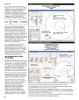
Circuit #2 Figure 3: Quarter Wave Transformer Match
This circuit (see Figure 3) demonstrates Quarter Wave Transformer Match
the operation of the classic quarter wave A 100 Load Resistor
transformer. Here I assume that the load 14 MHz
resistance is 100 Ohms and that the
characteristic impedance of the line is
70.7 Ohms with its length set to 90 degrees
at 14MHz. The input impedance seen by
the generator is 50 Ohms at 20 MHz
according to the following basic equation:
So let’s see if SimSmith agrees with the
basic formula. To do this I dragged a
transmission line into the circuit window
and set its characteristic impedance to
70.7 Ohms with a length of 90 degrees at
14 MHz. Here, the loss was set to 0 and its
velocity factor to 1 as seen in Figure 3.
SimSmith agrees with the basic formula, as
seen in the diagram. The load of 100 Ohms
is transformed through a path which
happens to be a circle that terminates in
the centre of the Smith Chart.
Figure 4: Inverted Delta Loop Antenna
You can experiment with this circuit in Vertical Delta Loop Antenna
many ways such as increasing the Load Data from EZNEC
transmission line loss or even selecting a L Match plus 4:1 Transformer
specifc transmission line such as a RG59 10.1 MHz Operation
from the transmission line type parameter Resonant Frequency 14 MHz
(Mdl) list under the transmission line
symbol. You will then see that the load is
not matched as well in this case.
AN INVERTED DELTA LOOP
HF ANTENNA
The fnal example used in this column is an
antenna that I am evaluating for use either
as a portable or a base station HF antenna.
This antenna is an inverted delta loop (see
TCA hotlink 4) fed at the bottom which is
designed to resonate at 14 MHz but
operated at 10.1 MHz in an attempt to use
it on different bands other than 20 metres.
The frst thing to note (see the parameters
under the Load L in Figure 4) is that the
simulated input impedance using EZNEC is
equal to 102 –j1080 Ohms at 10.1 MHz.
This capacitive reactance begs for the
addition of a series inductor to bring the
impedance close to the centre of the
Smith Chart. This is shown on the
inductance portion of the Smith Chart There is a lot of information available from the data given in Figure 4 above:
display. Then a shunt capacitance is 1) The input power is set to 1 Watt and the output power delivered to the antenna
added to bring the impedance to a equals 0.907 Watts which translates to a loss of 0.4 dB.
resistive value with no capacitive or 2) The loss in the tuning inductor is 0.052 Watts (5.2 Watts for a 100 Watt Transmitter).
inductive reactance as shown. Finally a This means that a fairly large powdered iron core will have to be used for the inductor.
simple 4:1 transformer with losses brings A large air core inductor could also be used.
the impedance to 50 Ohms as desired. 3) The loss in the tuning capacitor is insignifcant but its voltage is not yet determined.
4) The loss in the transformer is 0.18 dB (slightly optimistic).
16